Instruments turn off when starting engine having added extra battery,

Pye_End

Well-known member
Joined
5 Feb 2006
Messages
5,067
Location
N Kent Coast
Visit site
Sorry to disagree, but the normal setup for the 1-2-B switch is that the BOTH setting parallels the two batteries. The two circuits are both in parallel on settings 1 and 2

View attachment 174654
It is the negative arrangement in this diagram that I think some have in mind rather than the earlier one. Ie a shared cable rather than parallel. 2 circuits sharing a common -ve wire. Certainly this is the arrangement on my boat (not the +ve side though - I am not talking about that).

So, what would you see in terms of voltage drop at both the individual loads if there was a poor connection in the 'to all negatives' line when you turn the engine over, assuming the +ve sides are separate? Would you see a voltage drop in both circuits? It's hard to see how you wouldn't as you can't have 2 potential differences for the same wire. If so, would it be more apparent when you turn the engine over and you put a big load down it?

Do we know what the -ve arrangement is for the OP - I cannot see it? How do you know it isn't this one as so many seem to?
 

bedouin

Well-known member
Joined
16 May 2001
Messages
32,328
Visit site
BUT - you are saying that the negative lead from domestic is suffering from that voltage drop / load - even though the domestic + is not connected in any way or form to that load ... as far as the domestic is concerned - its an OPEN non connected circuit to the starter ... QED !

Ohms law has nothing to do with sheer simple physical lack of +ve connection !!
Let's try once more. Reminding you that this is on the assumption that there is an element of the -ve circuit in common but not making any assumptions about the +ve.

a) By Ohm's law - any wire is a resistor so any current flow in any wire causes a potential difference (Voltage Drop).
b) Significant current is flowing in the starter circuit meaning that the Voltage drop is not negligible.
c) That same voltage drop is shared by all circuits that include that section of wire.
d) Potential differences (Voltages) in a series circuit sum
e) Therefore the voltage seen by the instruments is reduced by the voltage dropped across its negative supply - equivalent to the voltage drop caused by the starting current in the common part of the circuit.

If you can tell me which of those you disagree with I'll try to explain.
 

B27

Well-known member
Joined
26 Jul 2023
Messages
1,174
Visit site
The OP has two separate circuits, one for the engine and one for the domestics.

They have a common negative, as do the vast majority of boats. This is typically so you can have an emergency parallel switch or for a battery monitor to correctly work, including taking into account the alternator charge going to the domestic batteries.

There is no connection between the positives of the two systems and they have separate isolators. The only time the OP will have a positive connection between the two systems is when the VSR is closed, creating a parallel connection between both systems. The OP has solar panels which could be creating enough charge to activate the VSR and and cause the batteries to be in parallel, hence the voltage drop on the domestic systems.

Without the positive connection it is absolutely 100% impossible to cause a voltage drop on one system by drawing any amount of current from the other system.

This is a typical system, similar to the OPs, you can clearly see there is no positive connection between the two banks unless the VSR is closed. :

View attachment 174653
If the diagram here is correct, then any voltage drop along the bus bar also affects the 'electronics'.
I think that's what Bedouin is getting at.
Other implementations may have move 'shared' negative wiring

But VSR needs checking out, try taking it out of circuit.

The voltage drop I referred to above can also be inductive.

IMHO, the negative of the engine battery is better wired straight to the engine, not passing go and not collecting 200mV.

If it's not any of that, then it could be some other interaction of the engine and domestic circuits. Are there any instruments or data networks on both circuits?? Engine gauges? Warning lights? Voltmeters? People could get caught out by subtle things like protection diodes which stop a data line going higher than a supply.

It's also not impossible that the plotter is being upset by a positive spike when the starter motor stops drawing power.


But my first look would be at the VSR. These things don't disconnect instantly when the volts drop!
Then I'd be checking that the plotter is not actually powered from the engine circuit after all...

You never know exactly how a boat is wired unless you did it yourself, and these days, that's not a guarantee either.
 

Buck Turgidson

Well-known member
Joined
10 Apr 2012
Messages
3,174
Location
Zürich
Visit site
Let's try once more. Reminding you that this is on the assumption that there is an element of the -ve circuit in common but not making any assumptions about the +ve.

a) By Ohm's law - any wire is a resistor so any current flow in any wire causes a potential difference (Voltage Drop).
b) Significant current is flowing in the starter circuit meaning that the Voltage drop is not negligible.
c) That same voltage drop is shared by all circuits that include that section of wire.
d) Potential differences (Voltages) in a series circuit sum
e) Therefore the voltage seen by the instruments is reduced by the voltage dropped across its negative supply - equivalent to the voltage drop caused by the starting current in the common part of the circuit.

If you can tell me which of those you disagree with I'll try to explain.
What does Ohm's law have to say about an open circuit?
🤦
 

bedouin

Well-known member
Joined
16 May 2001
Messages
32,328
Visit site
View attachment 174662

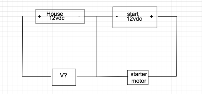
Where is the continuity in the house circuit through the starter motor? show me where those electrons are going?
You are confusing current and voltage.

The vertical line in the middle is shared between both. There is voltage drop across that wire that is equal in both circuits.

Redraw the diagram with that wire replaced by a resistor and it might make more sense to you
 

Buck Turgidson

Well-known member
Joined
10 Apr 2012
Messages
3,174
Location
Zürich
Visit site
You are confusing current and voltage.

The vertical line in the middle is shared between both. There is voltage drop across that wire that is equal in both circuits.

Redraw the diagram with that wire replaced by a resistor and it might make more sense to you
Nope. I don't need to. Show me how the load of the starter motor effects the house battery voltage.
 

bedouin

Well-known member
Joined
16 May 2001
Messages
32,328
Visit site
Nope. I don't need to. Show me how the load of the starter motor effects the house battery voltage.
You do need to because you clearly haven't understood.

This has nothing to do with the house battery voltage (I am really not sure where that idea came from - I certainly didn't suggest it) - it has to do with the voltage drop in the circuit. That is why you should draw a resistor - it might help you see that rather than getting all confused about mythical drops in the EMF of the battery
 

Buck Turgidson

Well-known member
Joined
10 Apr 2012
Messages
3,174
Location
Zürich
Visit site
You do need to because you clearly haven't understood.

This has nothing to do with the house battery voltage (I am really not sure where that idea came from - I certainly didn't suggest it) - it has to do with the voltage drop in the circuit. That is why you should draw a resistor - it might help you see that rather than getting all confused about mythical drops in the EMF of the battery
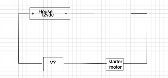
Screenshot 2024-03-29 at 12.18.23.png
You really do because Ive just removed the start battery so you can show me how the "voltage drop" in the negative lead will change for the house circuit?
 

Buck Turgidson

Well-known member
Joined
10 Apr 2012
Messages
3,174
Location
Zürich
Visit site
How can these two circuits run at different voltages when they share a wire? Does that wire know where the electrons came from and run down a different lane like a motorway?
The circuit voltage is the tension across the battery. The two circuits can and do operate at different voltages as everyone who has a boat with two circuits knows. Otherwise we would always see the same voltage on both batteries with common negatives.
 

Pye_End

Well-known member
Joined
5 Feb 2006
Messages
5,067
Location
N Kent Coast
Visit site
The circuit voltage is the tension across the battery. The two circuits can and do operate at different voltages as everyone who has a boat with two circuits knows. Otherwise we would always see the same voltage on both batteries with common negatives.
My apologies - I meant potential difference - ie voltage drop - across the common wire.

Imagine a poor joint in this line. At 1 or 2 amps this may not be apparent to the instruments, but suddenly chuck 300A say down it - what then? The potential difference (voltage drop) suddenly gets substantially higher - and the argument presented it that this has to affect both circuits. Hard to see why this would not be the case. I would like to see the maths.
 

Buck Turgidson

Well-known member
Joined
10 Apr 2012
Messages
3,174
Location
Zürich
Visit site
My apologies - I meant potential difference - ie voltage drop - across the common wire.

Imagine a poor joint in this line. At 1 or 2 amps this may not be apparent to the instruments, but suddenly chuck 300A say down it - what then? The potential difference (voltage drop) suddenly gets substantially higher - and the argument presented it that this has to affect both circuits. Hard to see why this would not be the case. I would like to see the maths.
The resistance of the wire doesn't change with current flow. It will change slightly with heat but that is self regulating as the current will drop as the resistance increases until it burns. This is not applicable to the case in point. The effect of the starter motor current will not change the resistance and therefore not effect the load in the house circuit. It will not cause a voltage drop in the house circuit. That will only happen if there is an increase in current in the house circuit i.e. it is feeding the starter. for this to happen the positive of the house battery must be connected in some way to the positive of the starter and the probable cause is the VSR in the OP's case.
 

billskip

Well-known member
Joined
6 Sep 2001
Messages
9,946
Visit site
View attachment 174662

Where is the continuity in the house circuit through the starter motor? show me where those electrons are going?
What bedouin is trying to explain (I think) is that when the initial surge excitement of the starter motor, momentarily there will be a spike on the negative, lifting the negative up to being positive, therefore being a lower pd, ie (for arguments sake)10V..this (I think what bedouin is trying to explain) makes the pd between the house +ve and the common negative actually 10v theoretically....I think that's what he is trying to say. The question is...would the pd drop momentarily across the instrument circuit of the house battery if the common -ve is spiked by the starter battery?
 

PaulRainbow

Well-known member
Joined
16 May 2016
Messages
15,827
Location
Suffolk
Visit site
How can these two circuits run at different voltages when they share a wire? Does that wire know where the electrons came from and run down a different lane like a motorway?
They share a single wire, the negative. Each circuit is a separate circuit, because the positives are separate.

On my own boat i have 5v domestic systems, 12v domestic systems, 24v domestic systems and 24v engine systems. They all share a common negative connection, accross all systems and three separate battery banks, 2 x 24v and 1 x 12v.
 

Buck Turgidson

Well-known member
Joined
10 Apr 2012
Messages
3,174
Location
Zürich
Visit site
What bedouin is trying to explain (I think) is that when the initial surge excitement of the starter motor, momentarily there will be a spike on the negative, lifting the negative up to being positive, therefore being a lower pd, ie (for arguments sake)10V..this (I think what bedouin is trying to explain) makes the pd between the house +ve and the common negative actually 10v theoretically....I think that's what he is trying to say. The question is...would the pd drop momentarily across the instrument circuit of the house battery if the common -ve is spiked by the starter battery?
yes. Post 36 and 37 address this.
 

bedouin

Well-known member
Joined
16 May 2001
Messages
32,328
Visit site
My apologies - I meant potential difference - ie voltage drop - across the common wire.

Imagine a poor joint in this line. At 1 or 2 amps this may not be apparent to the instruments, but suddenly chuck 300A say down it - what then? The potential difference (voltage drop) suddenly gets substantially higher - and the argument presented it that this has to affect both circuits. Hard to see why this would not be the case. I would like to see the maths.
Back of a fag packet calculation suggests of the order of 0.5-1 volt per metre of shared circuit, could be more with undersized cables or dirty connections.
 

PaulRainbow

Well-known member
Joined
16 May 2016
Messages
15,827
Location
Suffolk
Visit site
If the diagram here is correct, then any voltage drop along the bus bar also affects the 'electronics'.
I think that's what Bedouin is getting at.
Other implementations may have move 'shared' negative wiring
Of course the diagram is correct,, i have wired system up using it for more times than i care to count. A voltage drop on the engine circuit cannot possibly cause a voltage drop on the domestic systems as there is no positive connection, unless the VSR is closed.

Bedouin is talking absolute nonsense.
But VSR needs checking out, try taking it out of circuit.
I said that a long, long time ago, as did others. If the VSR is closed by virtue of the solar panels charging the batteries then it creates a parallel connection between the positives, meaning both systems are in parallel and voltage drop caused by starting the ening will, of course, be roughly equal on the domestic systems.
The voltage drop I referred to above can also be inductive.

IMHO, the negative of the engine battery is better wired straight to the engine, not passing go and not collecting 200mV.
This is not how boats are usually wired. The negatives are wired as per my diagram. If they are not you cannot have an emergency start parallel switch and your battery monitor cannot see the alternator charge current.
If it's not any of that, then it could be some other interaction of the engine and domestic circuits. Are there any instruments or data networks on both circuits?? Engine gauges? Warning lights? Voltmeters? People could get caught out by subtle things like protection diodes which stop a data line going higher than a supply.

It's also not impossible that the plotter is being upset by a positive spike when the starter motor stops drawing power.
How on Earth do you get a positive spike when the positives are separate ?
 
Top